Menu

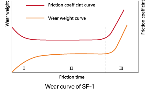
1)During the "running in" stage, the PTFE mixture on the surface layer is transferred to the mating surface to fill the concave pits and form a transfer film. At this time, the friction coefficient is high and the wear rate of the material is fast. As shown in curve I in the figure.
2)Stable wear stage: After running in, the friction becomes the friction between PTFE, with a low and stable friction coefficient, and a low and stable wear rate of the material. As shown in the curve of Zone II in the figure.
3)Rapid wear stage: The PTFE lubricant in the pores of the porous layer is consumed, making it difficult to obtain sufficient lubricant between the friction interfaces. Poor lubrication between the friction surfaces leads to a rapid increase in friction coefficient and a sharp increase in material wear rate, until 70% of the bronze is exposed, and the lifespan of SF-1 is approaching its end. As shown in curve III in the figure.
| Overall characteristics | Value | Unit |
|---|---|---|
| Basic information | ||
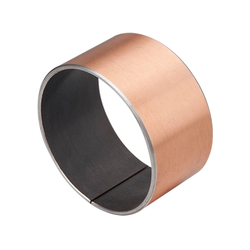
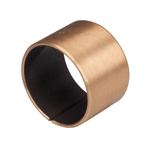
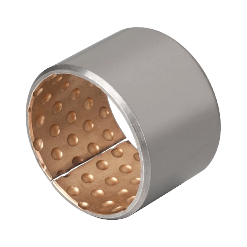
| Code name | SF-1W | |
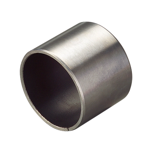
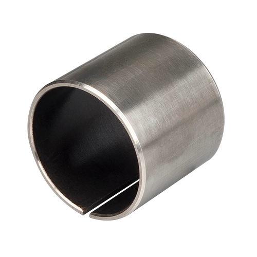
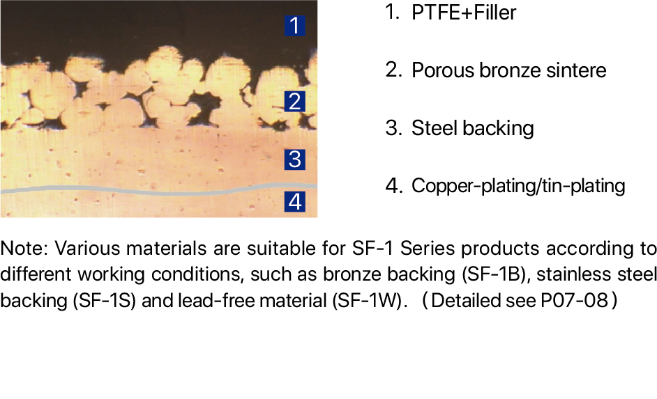
| Material | Carbon steel + Bronze + (PTFE + Filler) | |
| Main application areas | Medium and high-pressure gear oil pumps, plunger pumps, vane pumps, etc | |
| Maximum bearing pressure P (dry friction) | ||
| Static load | 250 | N/mm² |
| Dynamic load | 140 | N/mm² |
| Sway | 60 | N/mm² |
| Maximum linear velocity V | ||
| Dry friction | 2.5 | m/s |
| Oil lubrication | >5 | m/s |
| Maximum PV value | ||
| Dry friction | 1.0 | N/mm²·m/s |
| Oil lubrication | 10 | N/mm²·m/s |
| Coefficient of frictionμ | ||
| Dry friction | 0.08~0.25 | |
| Oil lubrication | 0.02~0.08 | |
| Matching shaft diameter requirements | ||
| Hardness HB | >220 | HB |
| Roughness Ra | 0.4~1.25 | |
| Physical properties | ||
| Operating Temperature | -200~+280 | ℃ |
| Thermal conductivity | 40 | W/(m·K) |
| Linear expansion coefficient (axial) | 11×10-6 | /K |
| External surface coating | Copper or tin | |